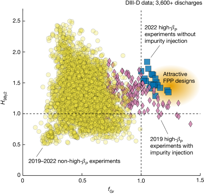
Fusion energy is the ultimate energy source for humanity16. A promising approach is a steady-state fusion reactor using magnetic confinement in the tokamak configuration17,18. With a deeper understanding of tokamak plasma physics and the development of reactor-relevant technologies, many fusion reactor designs have been proposed3,4,5,6,7,8,9,10. When the ion temperature is above 13 keV (1.5 × 10⁸ K) in D–T fusion reactions, the thermonuclear power density19 Pfus = nfuel2⟨σv⟩E/4 is proportional to the fuel density (nfuel) squared, as the change of normalized reaction rate ⟨σv⟩ with temperature is relatively small. Here, E is the fusion energy released per reaction. Detailed definitions of all variables mentioned in this paper can be found in Extended Data Table 1. Therefore, to achieve attractive fusion goals, most of the recent fusion pilot plant (FPP) designs require very high plasma densities, higher than the empirical edge density limit known as the Greenwald density11 (nGr), in tokamak high-confinement mode (H-mode) plasmas13. The energy confinement quality, represented by the H-factor20 (for example, H98y2), is believed to be the highest leverage parameter for fusion capital cost8. H98y2 is usually required to exceed the standard H-mode level (H98y2 = 1.0) for good fusion economy. FPP designs3,4,5,6,7,8,9,10 simultaneously require 1 ≤ Greenwald fraction (fGr) ≤ 1.3 and 1 ≤ H98y2 ≤ 1.65. However, such a tokamak operating regime is an uncharted area that has never been verified in experiments.
The empirical nGr is a density limit for the pedestal density in an H-mode plasma21,22. The pedestal is a narrow region of plasma at the edge with suppressed turbulent transport and a steep pressure gradient. When approaching nGr at the pedestal, various unfavourable phenomena can be observed in experiments. These cause a strong decrease of the confinement quality or even a sudden, complete loss of plasma energy (disruption)22. A peaked core density profile is, therefore, required to achieve a line-averaged density above the pedestal density limit. Possible approaches include relying on the natural peaking at low collisionality23 and the potential inward particle pinch24. The previous DIII-D experiment24 can achieve a transient fGr of about 1.4 with D2 gas puffing. A large pinch velocity has been measured. H98y2 in this case is around 1. ASDEX Upgrade experiments took a different approach by using pellet injection to improve the core fuelling. The experimental results show a transient fGr ≈ 1.5 with pellet injection25,26. However, the H98y2 values in those discharges were less than 1. More examples with H98y2 < 1 at high density are well documented22. As no tokamak experiment has yet attained a sustained fGr above 1 and H98y2 well above 1 (for example, 1.5) at the same time, experimentally verifying the desired operating regime in FPP designs is a great challenge for the magnetic confinement fusion community.
Another challenge with H-mode reactor plasmas is the very high transient heat load produced by quasi-periodic edge magnetohydrodynamic (MHD) instabilities known as type-I edge-localized-modes (ELMs). Without control, ELMs in a reactor can severely damage plasma-facing-components, for example, the first wall27,28. ELM control is an active research area and various approaches have been proposed29,30,31,32,33. However, compatibility among small/no ELM solutions, high density (above nGr) and high confinement quality (H98y2 well above 1, for example, 1.5) has not been demonstrated in experiments.
We report a new experimental approach for achieving a line-averaged density above nGr. It exploits an operating regime recently established in the DIII-D tokamak that allows simultaneous fGr > 1.0, H98y2 ≈ 1.5 and small ELMs and could support many existing designs for future reactors3,4,5,6,7,8,9,10. The approach elevates the plasma density in the core while keeping the pedestal fraction of the Greenwald density at moderate levels (for example, fGr,ped ≈ 0.7), thus not violating the empirical density limit. It does so by exploiting self-organized internal transport barriers (ITBs) at large minor radius in the high poloidal-beta (βP) scenario15,34,35,36. More information about the high-βP research can be found in Methods. In experiments, the on-axis fraction of the Greenwald density (fGr,0) can reach up to 1.7, resulting in a line-averaged fGr of 1.3. ITBs in the density and temperature profiles also greatly improve the energy confinement quality (H98y2 up to 1.8), compared to the standard H mode (H98y2 = 1) at the same engineering and operating parameters.
Figure 1 shows a plot of the DIII-D database and illustrates the progress made in extending the plasma operating space towards high fGr and high H98y2. The 2019 high-βP experiments with impurity injection15 have simultaneously achieved fGr > 1.0 and H98y2 > 1.0. However, in these experiments, too much impurity injection also increases the radiative energy loss in the plasma core, limiting H98y2 at high density. Of the violet diamonds in Fig. 1, some have H98y2 ≤ 1.2 when fGr ≥ 1.15. However, these results are not good enough for FPP designs. A major improvement in the 2022 DIII-D high-βP experiment used additional D2 gas puffing (Fig. 2) instead of impurity injection. This approach effectively reduces the core radiation and improves H98y2, as shown in Fig. 1 (blue squares). Thus, this paper reports a clear experimental demonstration of an accessible operating point in an existing tokamak that can meet a few of the FPP requirements, including simultaneous fGr > 1 and H98y2 ≈ 1.5. For comparison, other scenarios presented run on DIII-D have not achieved such simultaneous normalized performance (yellow circles).
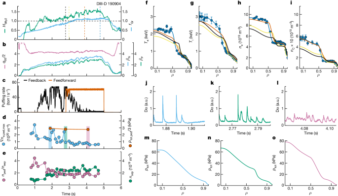
Figure 2 shows detailed data from an example discharge (190904) in 2022. The striking feature in this discharge is the dynamic synergy between energy confinement quality and plasma density. That is, H98y2 increased along with fGr (Fig. 2a) until the ramping down of the heating power (Extended Data Fig. 1e). This is opposite to the common observation of reduced energy confinement quality in higher density H modes22, especially for experiments close to the Greenwald density. The plasma was maintained at fGr > 1.0 and H98y2 > 1.0 for about 2.2 s, which was 2.2 times the current diffusion time (τR) or 24 times the energy confinement time (τE). Thus, the high normalized density and confinement phase was not transient, which is imperative for application in future long-pulse FPPs. A normalized plasma pressure βN ≈ 3.5 and βP ≈ 2.9 was achieved at safety factor q95 ≈ 8.5 (Fig. 2b) with plasma current Ip = 0.73 MA and toroidal magnetic field BT = 1.89 T, and with mixed co- and counter-Ip neutral beam injection (NBI). Note that nGr = 6.7 × 10¹⁹ m−3 in this discharge, close to the Greenwald density of the ITER 9 MA steady-state scenario at 7.2 × 10¹⁹ m−3. The dedicated D2 gas puffing time trace is shown in vermillion in Fig. 2c. This approach ensures that there is a sufficient source of particles in the plasma, and it pushes the plasma density to a higher level, regardless of the change in the feedback gas (black line in Fig. 2c).
Profiles of the temperature and density for electrons, deuterium (main ion) and carbon (main impurity) are shown in Fig. 2f–i and Extended Data Fig. 2a. The evolution of the on-axis densities for electrons, deuterium and carbon is displayed in Extended Data Fig. 1c. One can see that ITBs developed in all density channels. The increased deuterium density in this experiment suggests the promising application of this scenario in future FPPs, as it can attain a higher fuel density to give a higher fusion power. A related piece of experimental evidence is shown in Extended Data Fig. 1d. It is clear that with increased plasma density and energy confinement, the neutron rate, an indicator of fusion performance, increased substantially (67% higher, from 0.6 × 10¹⁵ to 1.0 × 10¹⁵ s−1) from 2 to 4.8 s, whereas the injected power (blue line in Extended Data Fig. 1e) was almost constant. Moreover, a very mild increase of the radiated power was observed in the very-high-density phase of the experiment (Extended Data Fig. 1e). The core radiated power as a fraction of the injected power increased from 10% to 20% as fGr increased from 0.7 to 1.1. The edge radiation remained about 25% of the injected power. Note that for either Bremsstrahlung radiation or impurity line emission, the radiated power was roughly proportional to the electron density squared. Therefore, some increase in the radiated power was expected even with the same impurity level, when the plasma density was increased significantly. Regarding the impurity behaviour, one can see a well-developed ITB at large radius in the carbon density profiles (Fig. 2i). Despite the ITB at large radius, the carbon density inside the ITB did not have a significant central peak, which would usually cause a large amount of core radiation and a reduction of core performance. The ratio between carbon density and electron density stayed around 4–5% during the evolution (Extended Data Fig. 2b). This is consistent with the well-controlled radiated power in the phase with fGr > 1.0.
The evolution of the safety factor profile (q-profile) is shown in Extended Data Fig. 2c. The figure shows the self-organized q-profile evolution, which reflects the change of the local bootstrap current density associated with the development of a large-radius ITB. The local minimum q (qmin) in the outer half of the plasma was at ρ ≈ 0.6 for around 2τR. qmin in this discharge stayed above 2.
When a density ITB built up over time and was sustained, the total pedestal pressure at ρ = 0.88 did not change significantly (Fig. 2d). However, other pedestal parameters and the ELM behaviour changed. At fGr < 0.8, typical standard H-mode pressure profiles and typical large type-I ELMs were observed (Fig. 2j,m). At 0.8 ≤ fGr < 1.0, pressure profiles with an ITB and compound ELMs emerged (Fig. 2k,n). Finally, pressure profiles with a large ITB and small ELMs dominated the fGr ≥ 1.0 phase (Fig. 2l,o). During the evolution, a decreased peak pedestal electron density (ne,ped) gradient, increased separatrix electron density (ne,sep) and decreased ratio between ne,ped and ne,sep were observed, as shown in Fig. 2d,e. These parameter evolutions are consistent with the favourable conditions needed to access the small-ELM regime discussed in the literature29. A more detailed modelling analysis of the pedestal for different ELM behaviours will be discussed later in this paper.
Although addressing the transient heat load is crucial, mitigating the stationary heat load is equally important for an FPP. Divertor detachment is widely considered to be a necessary solution for realizing an acceptable stationary heat load in the operation of future FPPs. Even without detachment-oriented impurity seeding, Extended Data Fig. 3 shows that the electron temperature at the divertor plates (Te,div) clearly reduced from over 35 eV (before 1.8 s) to 20–25 eV (1.8–2.8 s) and finally to 10–15 eV (after 2.8 s) in the fGr > 1.0 and H98y2 ≈ 1.5 phase, and there were small ELMs. The lowest Te,div phase is consistent with the existence of an ITB at large radius. Although Te,div ≤ 15 eV is not yet considered as divertor detachment (usually Te,div < 10 eV), it already suggests that there would be mitigation of tungsten erosion under the experimental stationary heat load, if a tungsten wall had been used. Note that although the integration of full divertor detachment and high-confinement core has been achieved in previous DIII-D high-βP experiments and reported15,37, the experimental approach and the operating parameter space were both different. The previous results used impurity seeding and fGr ≈ 0.9, which are not sufficient for FPP designs.
Therefore, the analysed typical DIII-D high-βP discharge has demonstrated a sustained, accessible operating point in a present tokamak that integrates high normalized density and confinement quality, small ELMs and reduced divertor electron temperature, thus addressing the key requirements of FPP designs for simultaneous high-performance core and excellent core-edge integration.
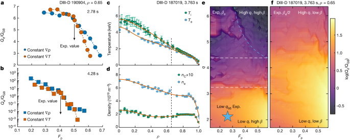
To understand the physics that enables high confinement quality at high normalized density, we performed a gyro-fluid transport analysis using the TGLF code38 on the experimental data from the discharge shown in Fig. 2. Figure 3a,b shows the dependence of the normalized electron turbulent heat flux Qe/QGB (where QGB is the Gryo-Bohm heat flux) on the fractional contribution of the density gradient to the pressure gradient (Fp = T∇n/∇p) at mid-minor radius in the plasma. The gyro-fluid modelling indicates that when using either numerical approach to vary Fp (constant ∇T or constant ∇p), the decreasing trend of Qe for increasing Fp is robust. A similar result was obtained for the ion energy transport. These results reveal an important feature in the high-βP scenario, namely that anomalous turbulent transport, which leads to poor global confinement, can be reduced with a high density gradient, that is, a high density in the core with the pedestal density maintained below nGr. This is consistent with the experimental observation of synergy between high confinement quality and high density. If Fp were increased by 30%, the normalized Qe would decrease by a factor of 2 compared with the prediction at the experimental value, when the normalized pressure gradient αMHD (approximately −q2/BT,unit2Rdp/dr) was moderate (1.13), as shown in Fig. 3a. However, the reduction of the transport can be 2–3 orders of magnitude stronger when αMHD is high (2.75) in the experimental equilibrium (Fig. 3b). Note that this finding is also consistent with the previous nonlinear gyro-kinetic theoretical modelling39, which found an extreme reduction in the transport coefficient when high αMHD was combined with moderate density gradients. The underlying physics includes 1) the low drive of the ion-temperature-gradient turbulence at high density gradient (that is, there is a low ratio between the density gradient scale length and the ion temperature scale length (ηi)), and 2) less effective coupling between trapped electrons and the trapped-electron-mode turbulence owing to the much narrower turbulence eigenfunction at high αMHD.
We also applied the same gyro-fluid transport analysis to a standard H-mode discharge to reveal the requirement for realizing the favourable conditions for low transport at high density. A low-q95 standard H-mode discharge (DIII-D 187019) with strong D2 gas puffing and high density was investigated. Compared with the high-βP discharge discussed above, this discharge had the same heating power (9 MW), comparable line-averaged density (5.0–6.5 × 10¹⁹ m−3), slightly lower βN (approximately 2.5), but much lower q95 (4 versus 8.5). This was because of a much higher Ip (1.3 versus 0.73 MA). Typical standard H-mode profiles are shown in Fig. 3c,d, which are different from the ITB profiles in Fig. 2. Figure 3e presents the transport analysis of a two-dimensional scan on Fp and local q at ρ = 0.65. The modelling uses the experimental βe value. As illustrated by the horizontal dashed lines, the figure can be roughly divided into three regimes. At low local q, such as for the standard H-mode experimental data point, the modelling predicts high turbulent transport at high Fp. This is consistent with the experimental observation of decreased H98y2 at high density in this discharge. At medium q, transport is predicted to be almost independent of Fp. Finally, low transport at high Fp can be found in the high-q regime (top right corner of this figure highlighted by the blue dashed line). This example suggests that a minimum of the local q ≈ 4.4 is required to access this regime. Note that the analysed high-βP case has local q ≈ 5.1. However, high local q alone is insufficient to access this regime. Figure 3f indicates the importance of sufficient βe, or the plasma pressure (β). Note that β changes accordingly in the modelling when scanning βe. The range of the two-dimensional scan is the same. However, this scan uses half of the experimental βe in the modelling. As one can see, the results are significantly different. For most of the q values in the scan, high turbulent transport at high Fp is predicted. The favourable low transport at high Fp may still exist but probably requires very high local q, which is less realistic in present tokamak experiments or future machine designs.
In summary, the transport analysis suggests that the standard H-mode could access the favourable low-transport regime at high density, with the following necessary conditions: high local q and high plasma pressure β, which are two key components in the expression of αMHD. Thus, sufficient αMHD is essential for realizing the favourable operating regime. As summarized in the literature15,37,40, α-stabilization is considered as the primary turbulence suppression physics in the high-βP scenario, as it provides a reactor-relevant rotation-independent mechanism for high confinement40. On the other hand, given that βP ∝ βNq95, high q95 and high βN lead to high βP. Therefore, the high-βP scenario is naturally an excellent candidate for pursing this goal.
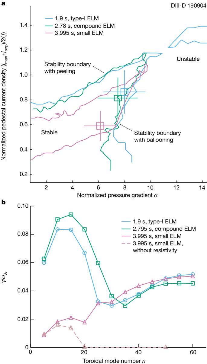
We performed a pedestal analysis to evaluate the pedestal stability and understand the evolution of the ELM behaviour in the high-βP discharge described in Fig. 2. The ELITE calculations41 shown in Fig. 4a predict the stability boundary for peeling–ballooning modes in the pedestal, for each of the three ELM states. In the type-I ELM state, the pedestal lies near the unstable ballooning region. Evolving to the small-ELM state, the experimental point moves along the ballooning boundary towards a lower pedestal pressure gradient and lower pedestal current density. Moving further away from the peeling boundary is consistent with the observation of no giant ELMs in the later phase. Modelling with BOUT++ (refs. 42,43,44) provides details on the instability growth rate in Fig. 4b. The dominant low-n peeling–ballooning mode was identified at n ≈ 10, which agrees with the ELITE result. The predicted low-n growth rate is smallest for small ELMs. BOUT++ modelling also resolves high-n resistive ballooning modes near the separatrix, when considering the plasma resistivity. It is clear that the high-n separatrix modes are dominant in the small-ELM case in contrast to other results in Fig. 4b. The modelling suggests that the high-n separatrix modes played an essential role in the observation of small ELMs in high-βP plasmas.
In this paper, we have extended the operating space of a tokamak plasma towards a regime with simultaneous fGr up to 1.25 and H98y2 ≈ 1.3–1.8, using the high-βP scenario in DIII-D. The achievement of entering this previously uncharted regime provides essential support to many attractive FPP designs all over the world. The increased deuterium density and neutron rate in the experiment confirm the promising application of this scenario for higher fusion performance in future FPPs. Unlike many previous high-density H-mode experiments, the high-βP scenario uniquely features a synergy between high confinement quality and high density, especially around the Greenwald value. We have also elucidated the important role of α-stabilization in this achievement, showing that the favourable regime of low turbulent transport at high density is predicted and achieved only at relatively high local q and high β, namely for sufficient αMHD at high βP. This successful experiment not only addresses a few of the key requirements on FPP core plasma parameters but also suggests a potential solution for core-edge integration by demonstrating sustained small ELMs together with fGr > 1.0 and H98y2 > 1.0. Realizing the small-ELM regime is understood as a combination of the reduced growth rate of low-n modes and the predominance of the high-n resistive ballooning mode near the separatrix because of the decreased peak density gradient in the pedestal, increased separatrix density and high βP. During the natural small-ELM phase with a high normalized density and confinement, the plasma is close to divertor detachment, which is believed to be the most promising solution for achieving steady-state plasma–wall-interactions in FPPs37,45. The natural proximity of detachment conditions shows the potential of a fully integrated scenario with high-performance core and cool edge. As the divertor detachment was not optimized in the discussed experiment, doing so will be important work for future experiments. Note that the compatibility of the high-βP scenario with full divertor detachment has been demonstrated37. So far, neither a significant central peak in the density profile of the impurity (carbon) nor a significant increase in the core radiated power has been observed when the density is above the Greenwald value. Dedicated impurity transport experiments and modelling work are also under consideration for this operating regime. Fast-particle confinement is important for future FPPs. Experiments on the high-βP scenario in DIII-D usually exhibit classical fast-ion transport. More discussion of previous results is presented in ‘DIII-D high-βP experiments’ (Methods).
We fully appreciate that further work is needed to address other critical issues related to FPP compatibility, for example, operating with a metal wall and helium exhaust. On DIII-D, limited experiments with high-βP plasmas operating with a divertor strike point on a (temporary) ring of tungsten tiles have shown promising results, with no significant degradation of core performance. However, to fully address the compatibility with a metal wall, we are collaborating closely with the Experimental Advanced Superconducting Tokamak (EAST) and Korea Superconducting Tokamak Advanced Research programme in the development of high-βP scenarios so that we can exploit their metal wall and long-pulse operation capabilities. Long-pulse operation (over 10 s) will further address the alignment for steady-state q-profiles and pressure profiles with ITB in the high-βP scenario. With regard to the helium exhaust, several review papers give favourable conclusions for high-βP plasmas with ITBs in JT-60U46,47. The results for JT-60U high-βP ITB plasmas show that the helium density in the core was controlled well and that no helium accumulation was observed, even with helium NBI for the core helium source. Moreover, the results also emphasize the importance of helium exhaust techniques, such as pumping, for controlling the helium content in the core.
Furthermore, there has been recent activity on extending the high-βP scenario towards true long-pulse operation, including modelling work for EAST48, ITER49,50 and FPPs under design10. Depending on the design philosophy of each group, the high-βP scenario can be applied in a wide range of FPP designs, from large conventional tokamaks14 to relatively small and compact devices9,10. One example from CAT-DEMO (Case D)9 shows a possible design point of an FPP using the high-βP scenario: R = 4 m, R/a = 3.1, BT = 7 T, Ip = 8.1 MA, q95 = 6.5, fGr = 1.3, fGr,ped = 1.0, βN = 3.6, H98y2 = 1.51, fusion gain Q = 17.3 and output electric power 200 MWe. The experimental achievement and the increased understanding reported in this paper may open a potential avenue to an operating point for producing economically attractive fusion energy.


